


Last week I sat down to write a Python script that takes any STL file and spits out a ready-to-print two-part injection mold. I figured an evening of work, maybe a few iterations to refine the parameters. Five rounds of bugfixes later, I had a working tool and a useful lesson: in computational geometry, do not trust your eyes.
https://github.com/GreenShoeGarage/InjectionMoldFromSTL
The setup
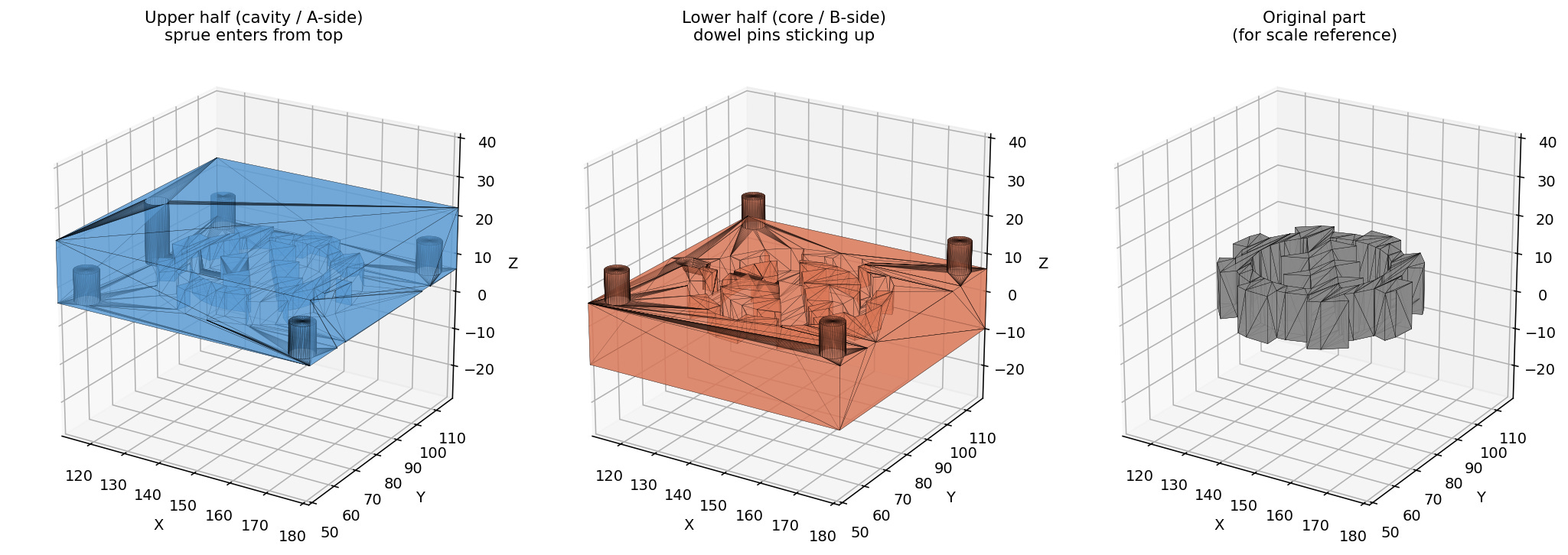
The premise was simple. Feed in an STL of a part. Get back two STLs, an upper half and a lower half, with all the features a real mold needs: sprue, runner, gate, vents, alignment dowels, optional ejector pins. The plumbing is mostly mesh boolean operations, and trimesh plus manifold3d handle that part well.
The first version was up and running fast. I tossed a gear STL at it, and it produced two halves that looked correct in any 3D viewer. Bounds were right. Watertight. Cross-sections through the parting plane showed a clean gear cavity, two vents, four dowel sockets at the corners. Job done, I thought.
It was not done.
Five bugs, in the order I should have caught them
Vents straddled the parting plane. I centered the vent box on the parting line, which meant each half got a 75-micron-deep slot. Geometrically present, functionally invisible. Real molds put the full vent depth on one half and let the opposite half’s flat parting face seal the channel.
Vents at evenly-spaced Y positions landed on tooth tips. A gear’s silhouette is mostly tooth tips reaching almost to the bounding box edge. Even spacing dropped one vent right where the tooth was practically touching the mold edge, leaving a stub two millimeters long.
Silhouette-aware placement still anchored the vent inner edge to the bounding box. When the silhouette analysis correctly found a deep tooth valley, the vent box’s inner edge stayed at a fixed offset from the bbox, sitting in empty space that did not overlap the part. Result: a slot in the mold, but no path to the cavity. Worse than the original bug, because it looked correct in renders.
Dowel pins at four-times-pin-radius from the mold edge ended up inside the part bounding box. Pin position collided with vent position. In a real mold this means plastic leaks past the alignment pin into the vent channel.
The vent’s bottom face sat exactly coplanar with the parting-plane cut. Boolean operations on coplanar surfaces leave non-manifold edges. The upper half came back with four broken faces and was no longer watertight.
Each fix exposed the next bug. Each bug had been invisible in the cross-section previews I had been trusting.
The lesson
After bug number three, I switched from rendering cross-sections to point-sampling the actual mesh. Pick a spot inside the slot, ask mesh.contains([[x, y, z]]). If it returns True, that point is solid mold material. If False, it is void. Run this at ten points along the slot’s path from cavity to mold edge. If any of them are solid, the slot is broken.
That single check would have caught bugs three, four, and five immediately. It is also the kind of test you can write into the build pipeline so the same bug does not come back later.
The renders are still useful for finding things you did not think to test. The tooth-tip vent placement was something I would not have looked for if I had not seen the picture. Eyes catch silhouette issues. Point sampling catches connectivity issues. Use both, but trust the latter.
What it does now
The tool slices the part at the parting plane to find the actual silhouette, places vents at the deepest tooth valleys, anchors each vent’s inner edge to its specific silhouette point, opens the slot through the parting face by extending the vent box across the plane by a micron, and puts the dowels in the padding region between the part bounding box and the mold edge. Both halves come out watertight. Both vents connect to the cavity. The audit script confirms it.
Five bugs and a lesson, and now a tool I can throw any reasonable part at and get a usable first-pass mold in seconds. Worth the evening, even if it took five.