For hardware engineers, creating an analog user interface (UI) with knobs, buttons, switches, LEDs, etc. is a relatively straightforward activity. By blending a bit of electrical and mechanical know-how, it’s rather easy to build interfaces between user and technology. From this hardware engineer's perspective, trying to develop a software-based user interface (GUI) is not nearly as straightforward. Back in the day, Visual Studio helped build desktop applications. MIT App Inventor was created to simplify the development of Android and iPhone mobile apps. However, creating a GUI for embedded electronics projects, such as Arduino or Raspberry Pi, has remained challenging, in my humble opinion.
I think it is because there is such a plethora of input devices, output devices, and processing hardware compared to smartphones' desktops, which are, for the most part, more limited. Or rather, they have a more defined set of I/O devices. A desktop is usually just a screen for output and a mouse/keyboard for input. A smartphone is a touchscreen that provides both input and output. However, embedded systems can have almost anything to serve as input. Sensors, buttons, switches, etc., come in a huge variety of options; thus, building a UI against such a diversity of potential hardware inputs is challenging.
Enter squareline.io
SquareLine offers a graphical methodology to create GUIs for embedded electronics projects.
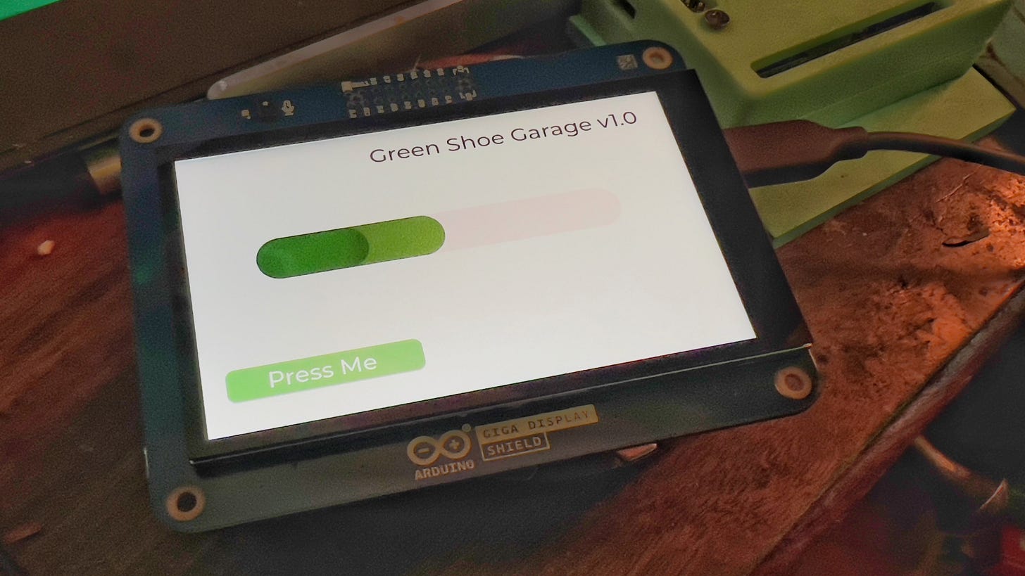
I wanted to see what it would take to create a GUI for the Arduino Giga display.
I wanted to take input from the touchscreen and cause an output in the real world. In this case, I tried pressing a virtual button on the display and turning on an external LED. Then, I wanted to take the output of a sensor and have its value change an object on the GUI display.
Accomplishing this goal was pretty easy. Let’s start with the SquareLine app to create the GUI itself. We will create a button that can be pressed to toggle an LED light onboard the Arduino Giga. We will also create a bar chart that will respond to a sensor reading.
From File > Project Settings > Export to set the folder root for project exports and UI files.
Open the folder the SquareLine generates and then navigate to the ui > ui.ino file and open that file in the Arduino IDE.
First, we need to update our sketchbook location in the Arduino IDE by navigating to File > Preferences and ensuring the file path is set to the folder generated by SquareLine
.Now let’s jump back and look at the code of ui.ino.
The setup function will set the LED_BUILTIN to an output and set it LOW (OFF) initially. We will use a variable ledState to track the current state of the LED as we wait for button pushes.
To change the value of the bar chart element in the GUI. We use this function:
lv_bar_set_value(target, val, LV_ANIM_OFF)
wherein
lv_obj_t * target tells us which UI element we are going to update; in this case, the value will be set to ui_Bar2
int val is the sensor value itself. In this case, we will simulate a sensor with a random number generator that will produce an integer value between 0 and 1023.
int LV_ANIM_OFF tells the display to update the bar element without animations. If you wish to enable animations, use LV_ANIM_ON instead.
The above will update the bar chart element on the GUI. Now, let’s turn our attention to responding to the button press to toggle an LED on or off.
The file containing the code we need to edit is in >project_root/libraries/ui/src/ui_events.c
We must tell the code to grab the global variable ledState defined in ui.ino, thus we use the extern keyword. Be sure to add the library “Arduino.h” as well. Then place the code in the HandleButtomHelpPressed() function as seen below.
And viola… the finished product:
Grab a copy of the Arduino code and the SquareLine project files here.


